Working platforms and piling mats
Temporary working platforms are important aspect of many construction projects, providing stable and safe working areas. Piling mats are working platforms designed specifically to carry the heavy static and dynamic loads from piling rigs, their support cranes and associated equipment.
Often placed over weaker subgrades, temporary working platforms are typically built using well-graded, compacted granular fill, such as natural gravels and crushed rock, as well as recycled demolition material. Geogrids can be incorporated in the granular material to stabilise it and increase bearing capacity, and platforms are designed to be free-draining, to prevent a build-up of water on the surface.
Contents
- The importance of safety
- Designing temporary working platforms and piling mats
- Design Guidance
- Verification of working platforms through plate load testing
- The benefits of stabilising geogrids in working platforms
- Tensar's T-Value Design method
- How T-Value differs from other design methods
- Verification of the T-Value design method through laboratory testing
- Verification of the T-Value design method through field trials
- Applying the T-Value design method in practice at Beverley WWTW
- Acceptance of the T-Value design method

The importance of safety
The UK’s Federation of Piling Specialists (FPS), estimates that a third of all dangerous occurrences reported by its members are related to piling mats – a soft spot just 1m2 can cause a rig to topple, with the potential for devastating consequences. Safety in design, construction and maintenance is obviously of paramount importance.
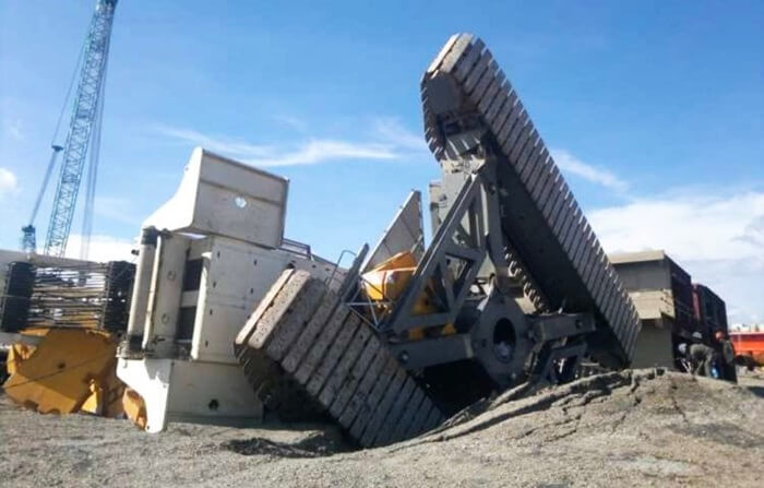
Source: http://www.heavyliftnews.com/accidents/tragic-crane-accident-vungtau-vietnam
The FPS recommends that piling mats should be inspected daily to ensure they are in proper working condition. If any excavations, trenches or holes have formed in the surface, they must be properly backfilled to ensure they are as stable as the rest of the mat.
Every site with an operational piling rig has to have a Working Platform Certificate, which confirms the piling mat has been properly designed, and constructed in accordance with the design, and that it will be regularly inspected and maintained. This is signed by the principal contractor and provided to the piling contractor before work starts.
Designing temporary working platforms and piling mats
Temporary working platform design should be carried out by a competent person, and preferably a geotechnical engineer. Design depends on ground conditions and the groundwater regime, and so requires sufficient ground investigation data.

Platform thickness depends on subgrade strength, the platform materials and, of course, the expected construction loads – piling machinery, in particular, is some of the heaviest on site. It is important to have a platform that can provide sufficient bearing capacity for safe working, while being economic and straightforward to construct.
If the platform is being built over particularly loose and weak soils, additional ground treatment may be needed before it is built.
Design guidance for working platforms and piling mats
The key document for UK designers is BR470 Working platforms for tracked plant, which includes guidance on the design, construction, operation and maintenance of working platforms. It was written by the Building Research Establishment under the direction of the FPS.
In 2011, BRE published a supplementary document, Use of structural geosynthetic reinforcement – A BRE review seven years on. This recognises that alternative design methods can be used, including platforms built using granular material mechanically stabilised with geogrid, as long as designs are based on ‘credible and representative’ research and project case studies.
Other guidance includes:
- Federation of Piling Specialists Guide to Working platforms
- The European Federation of Foundation Contractors and Deep Foundations Institute’s A guide to working platforms
- The Institution of Civil Engineers Temporary Works Forum’s Working platforms – Design of granular working platforms for construction plant – A guide to good practice
Verification of working platforms through plate load testing
BR470 recommends that the design and construction of working platforms should be carried out using plate load tests.
A plate load test involves the increasing loading of a circular steel plate placed on a ground surface and measuring the settlement induced, to determine bearing capacity.
Plate load tests typically use 0.3m or 0.6m diameter plates, with the size of the pressure bulb created (and therefore the depth of ground being tested) being related directly to the size of the plate – typically twice its diameter (so about 0.6m depth for a 0.3m diameter plate).
If two tests using different size plates are carried out on the same piece of ground, the results will differ, as the volume of soil being tested is different. This can cause issues when plate load testing a working platform, where there are two distinct layers: a stronger, compacted granular material layer over a weaker subgrade.
If the platform is thicker than 0.6m, then a 0.3m diameter plate load test will only determine the bearing capacity and settlement characteristics of the granular layer and not of the weaker ground beneath.
So, while results from tests using 0.3m diameter plates can be used for quality control – to check the platform has been compacted correctly and meets specification – they are inadequate for assessing the safe bearing capacity of the platform.
A better approach, and one Tensar advises, is to use a larger plate closer in size to the width of the load imposed by the construction equipment (field testing used to verify the T-Value design method used a 1m2 plate).
This means the test will create a pressure bulb similar in size, and depth, to the one created by a rig’s tracks. As a result, the settlement characteristics of both the platform and subgrade will be measured, giving a more accurate assessment of its ultimate (and safe) bearing capacity.
The benefits of stabilising geogrids in working platforms
Incorporating stabilising geogrids in the granular material used to form a working platform can improve bearing capacity, while being up to half the thickness of a non-stabilised granular layers.
This is because of the interlocking mechanism and particle confinement that develops between the aggregate and the geogrid. This prevents lateral movement of the granular material, creating a mechanically stabilised layer that increases bearing capacity and controls differential settlement.
Additionally, lower quality and recycled granular fill can be used and together, this can save time and money through reduced excavation and imported materials, as well as reducing the platform’s carbon footprint.
However, while the 2011 supplementary document to BR470 Use of structural geosynthetic reinforcement – A BRE review seven years on, considers geosynthetics, because their effects are based upon individual manufacturers’ guidance, this can lead to inconsistency and uncertainty for designers and engineers carrying out design checks.
This can mean that geosynthetics are not specified, so potential benefits and savings are missed. This missed opportunity led to the development of the Tensar T-Value design method.
Tensar’s T-Value design method
Tensar’s T-value design method enables a more accurate assessment of the positive effect of stabilising geogrids on the bearing capacity of a granular working platform.
Applicable to a range of working platform materials, in different ground conditions, the method allows designs with, or without, geogrid to be compared, including for very low subgrade shear strengths. It can also be applied to surface and shallow embedded foundations, with dry or saturated granular layers.
The T-Value design method is based on the relationship between the bearing capacity and load transfer efficiency of the granular layer. This is expressed as a T-value, which depends on the shear strengths of the granular layer and the subgrade beneath. While scientifically rigorous, the method is simple to use with measurable input parameters (ie the coefficient of friction and undrained shear strength).
This means that, for the first time, the full benefits of stabilising geogrids can be incorporated consistently in designs for working platforms. It delivers verifiable designs that can reduce platform thickness and improve bearing capacity, cutting construction costs by up to 30% and reducing a platform’s carbon footprint by up to 40%.
How T-Value differs from other Piling mat design methods
While BR470 considers geosynthetics, their effects are based upon manufacturers’ guidance, which can lead to inconsistency and uncertainty during design checks. Existing methods are either overly-simplified (eg a common load spread angle for all cases) or use obscure, hard-to-understand empirical input parameters.
Furthermore, a granular material’s bearing capacity and a geosynthetic’s tensile strength are considered separately. This is inappropriate to stabilising geogrids because, as discussed, rather than acting in tension to reinforce granular material, the aggregate and geogrid perform as a composite, due to interlocking and particle confinement in the geogrid’s apertures.
What makes the T-Value design method different from other methods is that, for the first time, the performance of a composite of granular material and stabilising geogrid can be analysed. This gives a truer prediction of performance and also allows designers to compare this performance with that of non-stabilised materials.
While in theory, the T-Value Method can be applied to other granular materials and geogrids, the relationship between the T-Value and subgrade strength that has been derived is for Tensar geogrids alone. If other aggregates and geogrids are to be used, the relationship must be derived through FEA and laboratory testing and validated using full-scale testing appropriate to the platform or foundation being built.
Verification of the T-Value design method through laboratory testing
The T-Value design method was developed using finite element analysis (FEA) of granular layers stabilised with geogrid.
However, FEA models used in geotechnical design characterise geogrid in terms of its in-air tensile stiffness or strength properties, together with the mechanical characteristics of the soil without geogrid, often measured using triaxial tests.
This can lead to significant under-prediction of stabilisation geogrid performance, because this depends critically on the mechanical interlock between the aggregate particles and the geogrid apertures.
Triaxial testing of the aggregate and geogrid together overcomes this, as it enables the performance of a composite material to be measured. Testing has to be carried out at a much larger scale to overcome particle size effects, typically on 0.5m diameter, 1m long samples, with a single disc (or more) of geogrid placed at the midpoint of the dry, compacted aggregate.
Tensar used large scale triaxial testing on different combinations of aggregate and geogrid to verify that the stabilisation effect could be measured, as part of the development of the T-Value design method.
A total of 500 tests were carried out and results showed that peak shear strength in geogrid-stabilised aggregate was enhanced, compared with non-stabilised aggregate. In other words, more stress was needed to shear and dilate the sample and larger strains were needed to cause significant softening of the stabilised granular material, compared with the non-stabilised material.
Verification of the T-Value design method through field trials
The T-Value design method has also been tested in the real world, with Tensar teaming up with the University of Saskatchewan in Canada to carry out full-scale plate load tests of a trial section of granular working platform on a clay subgrade.
Testing, using two 20t trucks as a reaction force, was carried out on 0.25m and 0.5m thick granular platforms, on sections with, and without, stabilising geogrid.
A 1m square plate was used to create a pressure bulb similar in size, and depth, to the one created by the track of a piling rig or crane. This, gave a more accurate assessment of ultimate (and safe) bearing capacity of the platform, compared with conventional tests using 0.3m or 0.6m diameter plates.
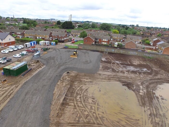
Applying the T-Value design method in practice at Green Park Primary Academy
The T-Value design method enabled design and construction of two working platforms for the construction of Green Park Primary Academy in King’s Lynn, when very weak ground meant standard approaches could not be used.
Norfolk County Council awarded the £8m design and build contract for the new academy to Cocksedge Building Contractors.
Consultant Richard Jackson was tasked with designing two working platforms, covering a total area of 2,150m2, to support a maximum load of 272kPa from the rig carrying out ground improvement of the underlying highly variable and very weak peat and clay soils. The platforms also provided access for the piling rig installing foundations for the school buildings.
However, the underlying soils’ minimum undrained shear strength (Su) of 9kPa fell outside BR470 guidance, so Tensar was asked to provide a solution to allow piling operations to take place safely.
The T-Value design method produced the designs for the working platforms, one for the area with a minimum Su of 9kPa, and another, where the minimum Su was 25kPa.
Designs were based on rig loadings, soil conditions and granular fill grading. On-site validation testing confirmed the T-Value design method accurately predicted safe bearing capacity at the top of the working platforms, built using 6F1 aggregate, mechanically stabilised with Tensar geogrid.
The platforms were successfully installed and, based on a comparison with similarly derived non-stabilised platform thicknesses, saved around 35% in construction costs, 20% in construction time and around 50% in carbon emissions.
Download the case study of Green Park Academy project here.
Acceptance of the T-Value design method
The T-Value design method has been welcomed by industry, having been used on projects around the world since its introduction in 2019. Additionally, a number of academic papers have been published in industry journals, outlining the theory behind the method:
- Bearing Capacity of geogrid-stabilised granular layer on clay, Ground Engineering Magazine 10 October 2019
- The bearing capacity of a granular layer on clay, Proceedings of the Institution of Civil Engineers - Geotechnical Engineering Volume 173 Issue 1, February, 2020
- Strength envelope of granular soil stabilized by multi-axial geogrid in large triaxial tests, Canadian Geotechnical Journal, 18 April 2019
- Working platforms for tracked plant – BR 470 guideline and a revised approach to stabilisation design with multiaxial hexagonal geogrids, Conference: 13th Australia New Zealand Conference on Geomechanics, At Perth, Australia April 2019
Design with confidence, from anywhere.
- Design & evaluate pavement and gravel sections
- Easily compare alternative materials
- Determine initial and lifecycle cost savings, time savings, and sustainability metrics
- Create high-level summaries of the design alternatives for project stakeholders
- Share features that aid collaboration